Overview
The testing for the project will take place during spring quarter of 2021. The main goal of testing for this project is to make sure that it meets the requirements that are needed to not only be functional, but efficient and durable as well.
The main test of this device is making sure that it can effectively transfer the power from the electric motor and handle the torque created by the reduction boxes, while crushing the carbon fiber strips. This means that it will have to be able to transfer 2000 ft-lbs. of torque from the final reduction box to the crusher shafts. While running, deflection will also be checked in the crusher housing to see how well the chain drive is tolerating misalignment.
Various other requirements will also be tested, such as allowable deflection will still transferring power, noise level, and estimated chain life.
Initial Wood Test |
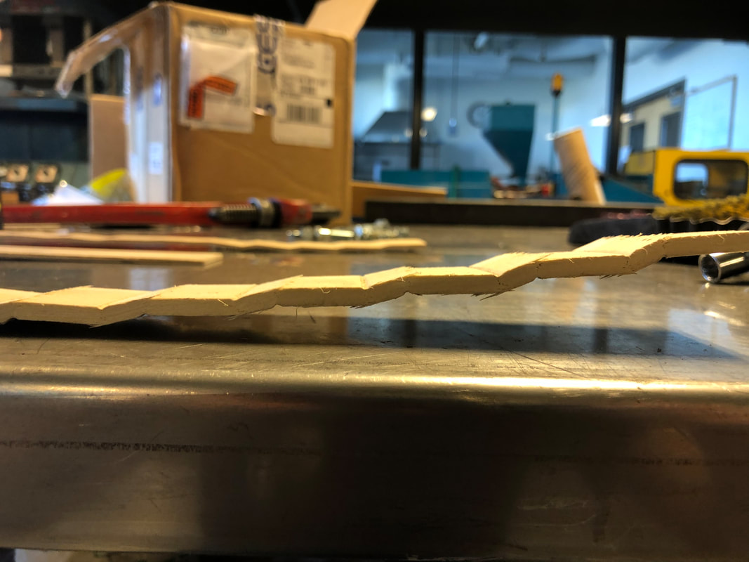
The first test done involved running the crusher by hand, and using wood as the material to be crushed rather than carbon fiber. This allows for a low load to initially test the drive system. By using a low load to test, it is possible to check for issues without potentially overloading a component that needs adjusting or modification. Below is a video showing the process, and the resulting crushed wood strip.
|
Left: Resulting wood strip, which was crushed easily. The test did later reveal an issue with some play on the shaft in the lower crusher spur gear. This will be addressed before further testing of the crusher.
|
Backlash Test
Next, the backlash in the spur gears was tested. In tests from last year, the some lower spur gear's teeth were destroyed during testing. The JCATI team believes this could stem from the gears not being set up with proper backlash. During reassembly this year, the pillow blocks holding the shafts were adjusted to allow for fairly tight backlash on the spur gears.
|
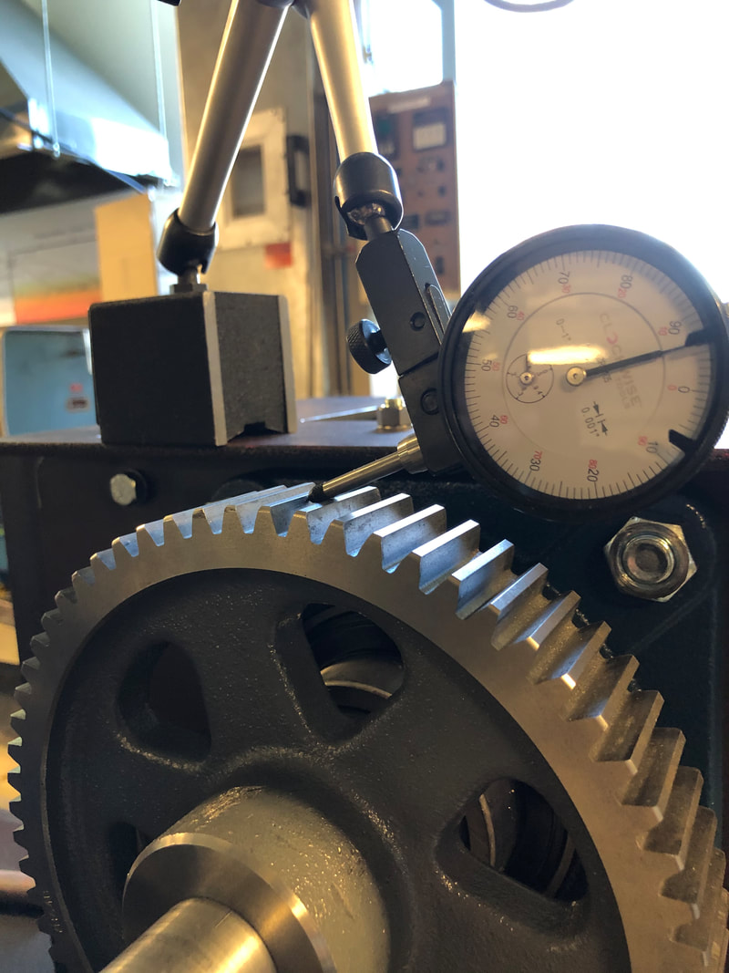
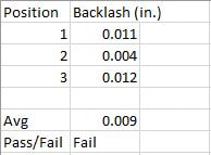
To the left is an image of the setup for testing the backlash. The bottom gear is held in place tightly will the top gear is rotated from engagement on one side of the engaging teeth to the other. This was checked in three different locations on the gear, about 120 degrees away from each other. Below is the data sheet for the test. To pass, a consistent value of .005 in. is needed.
|
Below is a video describing the test, predicting results, and the process. Note: Updates will be made to the video once backlash is corrected.
Corrected Backlash
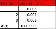
The above test was redone after adjusting the backlash again, and it now passes the test. Once the backlash was corrected, two roll pins were installed in each pillow block and into the crusher housing so that the pillow blocks are less likely to move under load. After further testing which will be discussed later, the pillow blocks have shown to maintain backlash with the addition of these pins.
|
To the left is a table showing the new backlash values. All values are under .005", so it now passes the test perfectly. This value of .005" is the recommended backlash for a gear with a pitch of 8, so it is applicable to these gears.
|
No Load Friction Torque Test
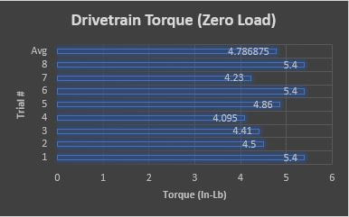
The next test was done to check for binding within the drive system. The whole drivetrain needs to have smooth operation. This was done by attaching a digital fish scale to the manual hand wheel, and pulling just until it begins to rotate. This minimum torque to rotate the system was then recorded, and calculations were done to find the input torque required. This test was done at eight different locations throughout the rotational travel of the drive system to thoroughly ensure smooth operation. Torque should not exceed 10 in-lb.
|
Shown to the left is a char of the the resulting input torques required. With an average of 4.78 in-lb. and a max of 5.4 in-lb., it easily passes the test.
Just to put into perspective and validate how little torque this is, the 5hp motors used for this project can pump out 180 in-lb. of torque. 5.4 in-lb. of torque will be overcome as if the friction load is non-existent. |
|
Crushing while Powered
After these initial tests were done, it was nearly time to test while using the electric motor to run the crusher. VFDs were installed to aid in control of output speed and torque from the electric motors that run both the crusher and the shredder. Partially delaminated carbon fiber strips were used to begin to lower the load for this initial test under power. To pass this testing, the shredder would need to crush partially delaminated material as well as raw full thickness material.
Testing showed that there are some internal problems within the crusher. The system would load up and unload violently, causing worry about component failure. This problem will be addressed, and video of further testing will be uploaded at that point.
Testing showed that there are some internal problems within the crusher. The system would load up and unload violently, causing worry about component failure. This problem will be addressed, and video of further testing will be uploaded at that point.
Overall Results
At this point, the device is showing much improvement over last years version but it is still not completely successful. Time needs to be spent solving the issue of the crusher loading and unloading. Once this issue is fixed, it is expected that it should function correctly and full carbon strips will be able to be delaminated.
