|
Description of MethodsThis project is a continuation of an existing design done by previous students at CWU. Many parts for the project have been purchased, and new parts will be as well.
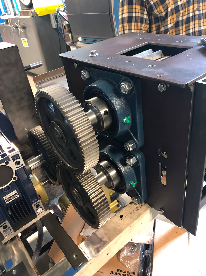
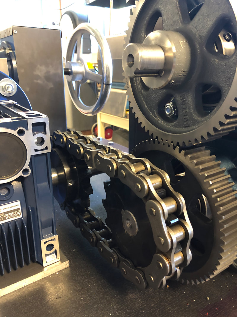
Many decisions have been made about how to go about improving the existing design. Through analysis, it has been decided that a chain drive from the reduction box to the lower crusher shaft would be beneficial. Description of ConstructionPictured to directly to the left is the original design of the crusher. This design has had binding issues, and using a chain drive is hoped to help eliminate that issue.
In order to fit both a spur gear and a chain sprocket on the bottom shaft, the hubs will have to be milled down to reduce overall width. |
Crusher Shaft Modification |
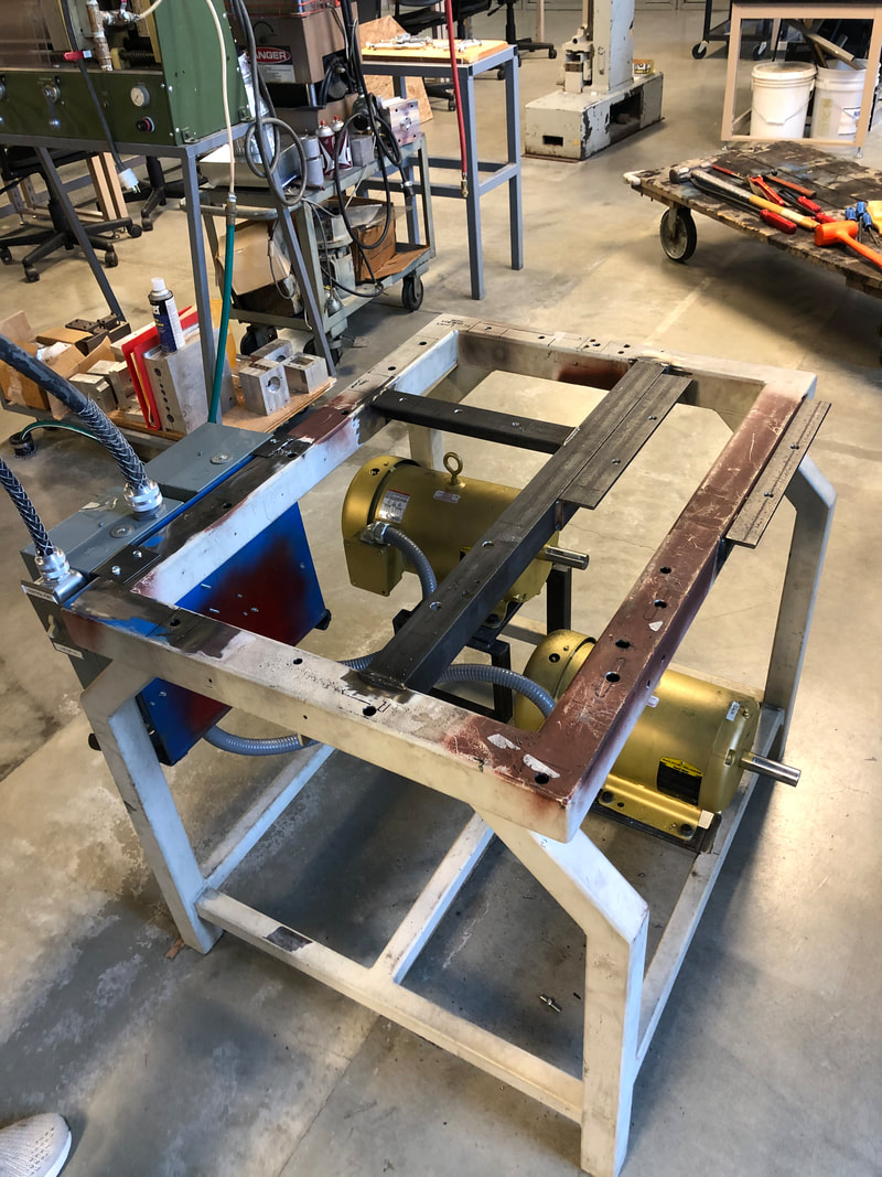
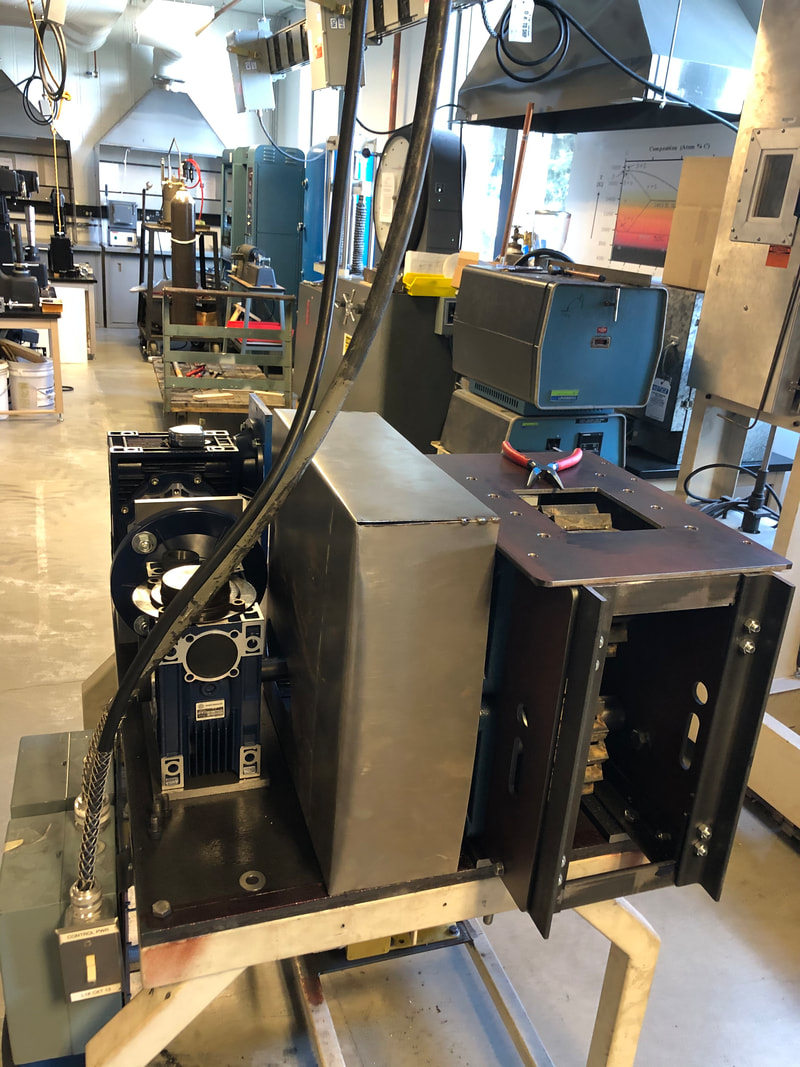
To the left is an image of the bare table that the assembly is placed on. At this point in construction, the table has been stripped for a 3/4 inch steel plate to be place over the entire surface to add rigidity.
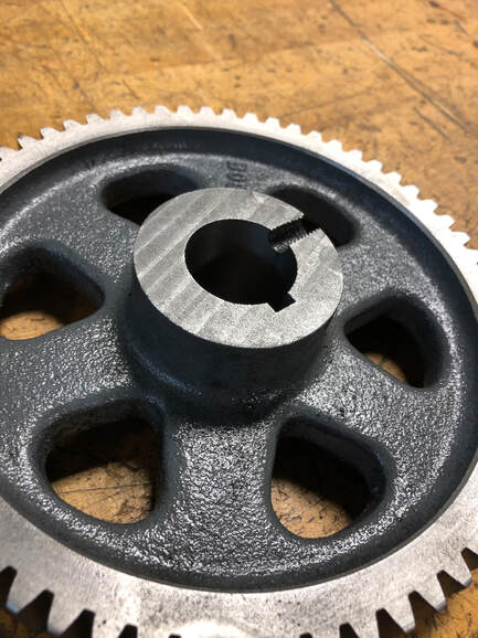
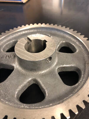
Construction will continue throughout the winter quarter and the chain drive will be assembled once the plate is secured to the table and the components are fastened down. Spur Gear ModificationPictured to the left is the lower spur gear after the hub has been milled down in order to fit both this spur gear and the chain sprocket on the lower crusher shaft. Below is the same spur gear after re-drilling and tapping the set screw hole.
|
|
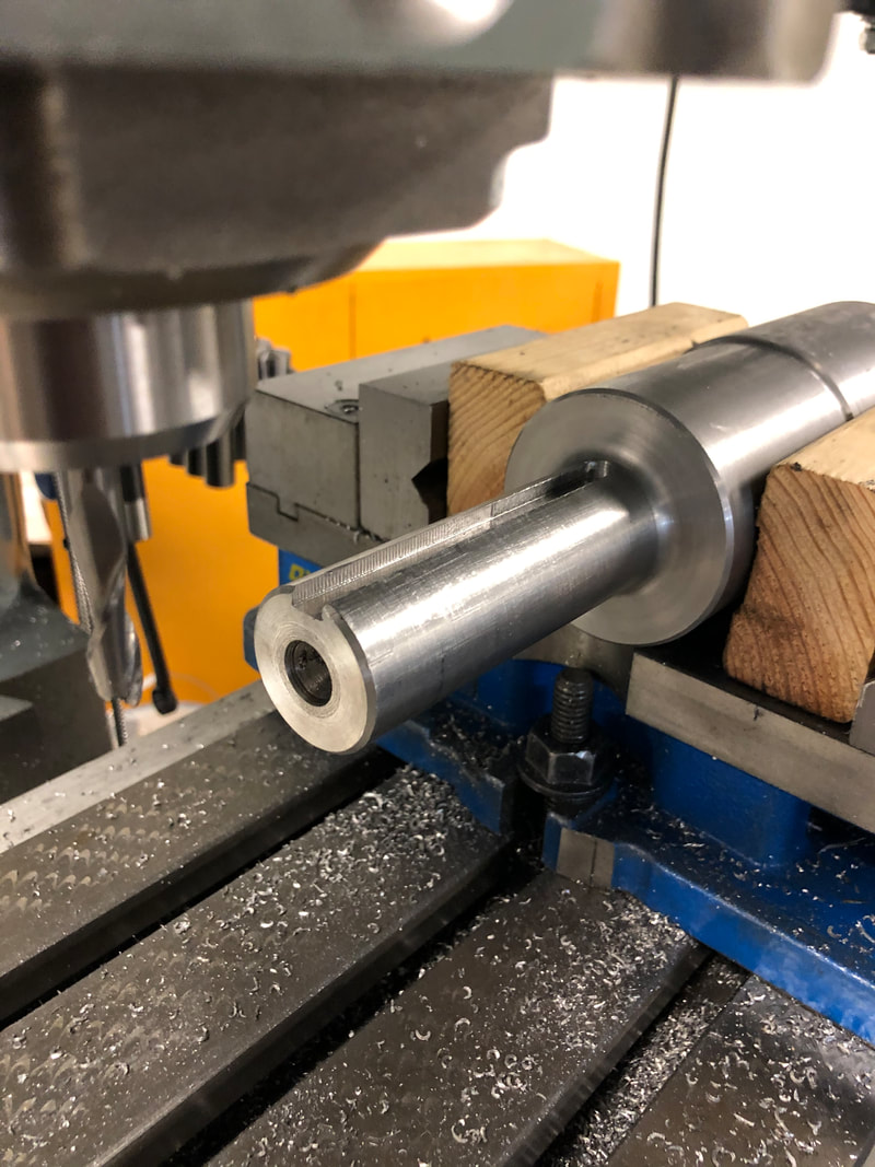
After the spur gear was modified, the next task was to extend the keyways on the crusher shafts. This was done in order to allow for the spur gear to be positioned inward on the shafts, and allow for room for the lower sprocket. The keyways were extended in the mill by setting them up perfectly level and with the existing keyway centered at the top of the shaft (Shown right).
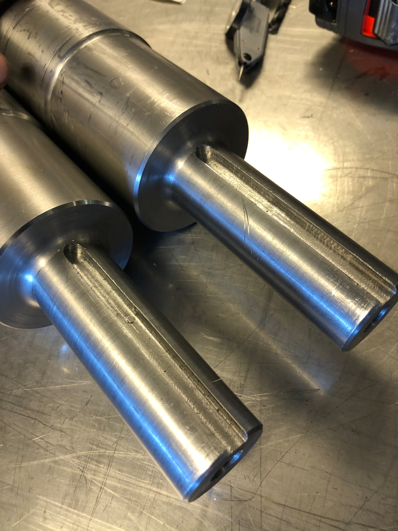
The image to the far right shows the completed keyways. |
|
|
Table Top Plate Manufacturing
In order to get to the point that this portion of the project can be assembled, Jacob Atamian has needed help with manufacturing of his top plate. This 3/4 thick plate is being utilized to help control deflection, and to allow each component to be more securely and accurately fastened. Below links to a few videos showing the milling process to make a cutout for the electric motor drive chain to fit through.
| Milling Plate |
| Milling Plate 2 |
| Milling Plate 3 |
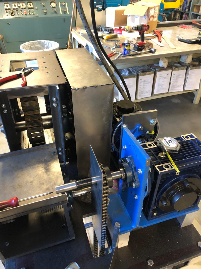
Reassembly
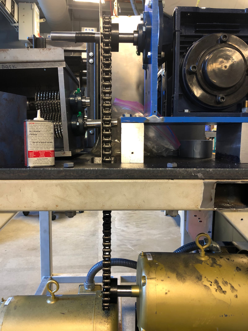
The first component that needed to be installed for assembly was Jacob's top plate. Then the crusher needed to be put back together with the modified shafts and spur gear. Once these components were installed and put together, the rest of the drivetrain was fastened to the plate. Ben Cooley's shredder was also installed, as well as chain from the electric motor to the first reduction box. This portion of the project was last to be installed (Shown below left).
|
|
|
|
