Requirements
In order for the drive system to effectively run the delamination "Crusher" gears and have a continuous feed capability, it will need to meet some requirements.
- Capable of transferring 2000 ft lbs. of torque without slippage
- Allow for .063 in of deflection without binding or slippage
- Capable of running at full 1750 RPM of electric motor (2.6 RPM at crusher shafts).
- Able to transfer the power of the 5 hp motor without binding or breaking.
- Continuously feed carbon fiber trimmings without interruption.
- Chains should last for at least 5000 hours of run time.
Description of Analyses
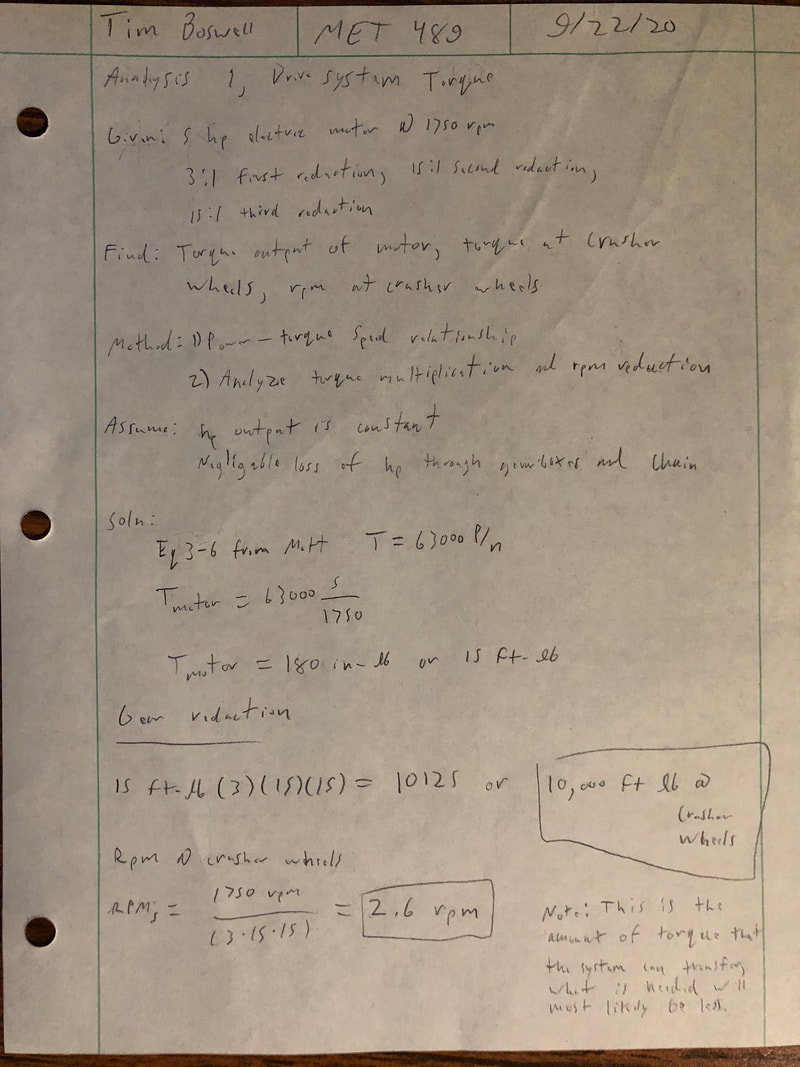
Analysis 1 was done first to find out how much torque the gear reduction system and electric motor are able to produce. The rpm at the end of the gear reduction was also found. Calculations showed that the maximum torque output is 10,000 ft-lbs, and the 1750 rpm at the motor was reduced down to 2.6 rpm.
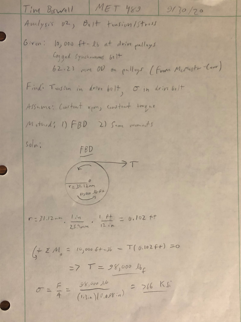
Analysis 2 was done to find out how much tension and stress is in the belt at maximum torque. This came out to be 98,000 lbs of force, and an internal stress in the belt of 766 ksi. It is important to note that more analysis needs to be done to find if the process will ever actually use this much torque, and how much stress is in the belt under normal operating conditions.
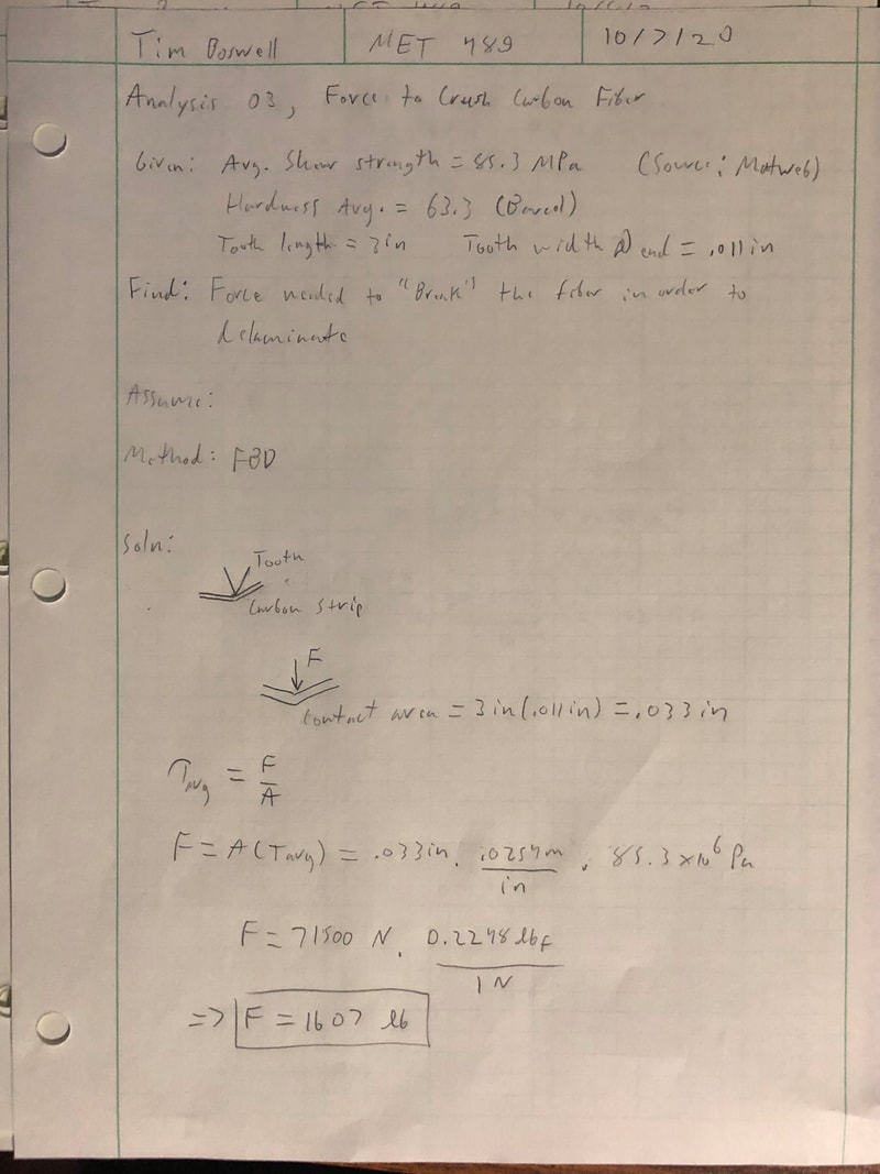
Analysis 3 was done to find the amount of force to “shear” the carbon fiber. This should help to later find the amount of torque needed to rotate the crusher teeth into the fiber. This was done by finding the area of the end of a crusher tooth, and then using the formula for average shear stress to solve for the force needed.
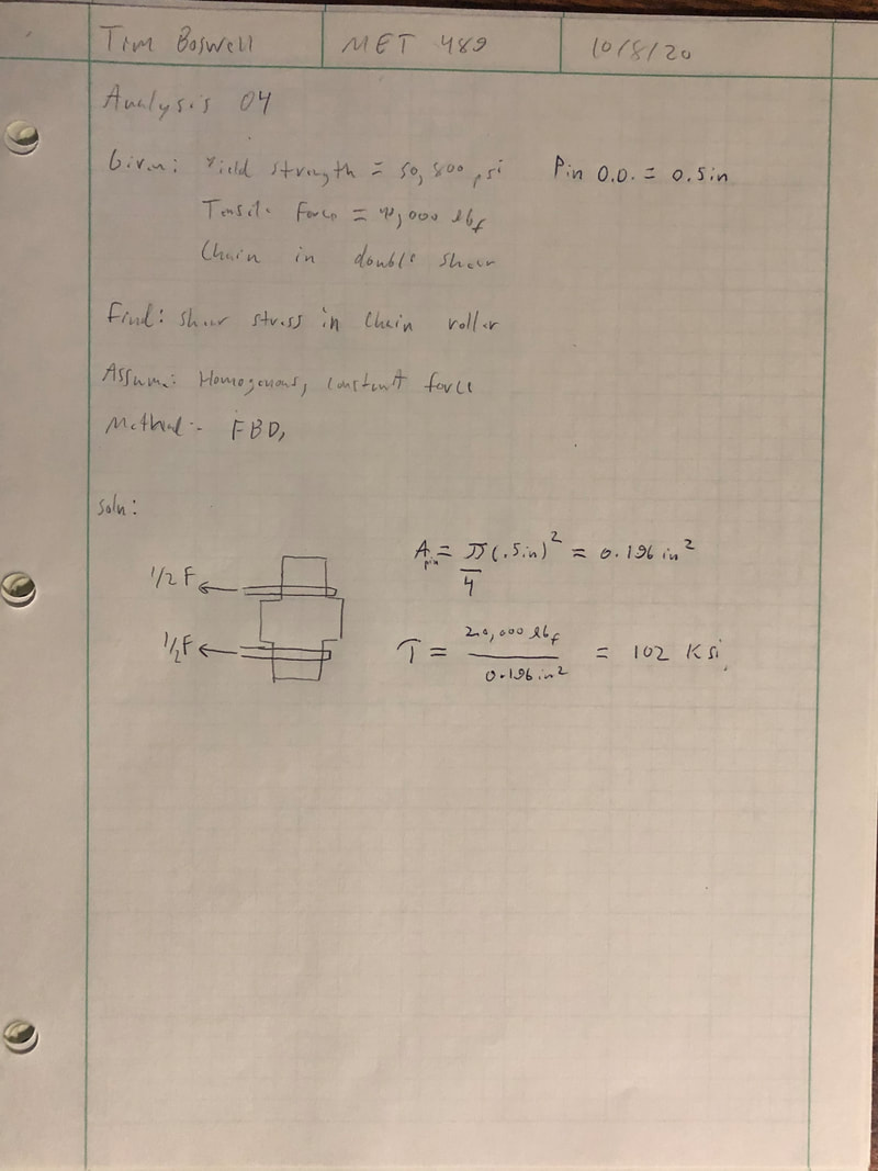
After selected the needed chain size, Analysis 4 was done to make sure that the chain could in fact handle the load. The chain rollers are in double shear, so that was considered. The cross-sectional area of the pins was calculated, and F/A was used to find the shear stress in each pin.
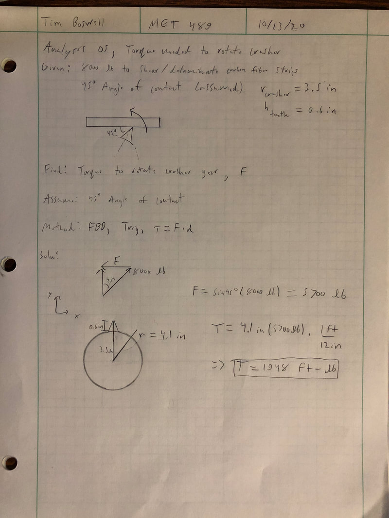
In order to find out whether or not a smaller chain could be used, more analysis was needed. This started with Analysis 5 to find the torque needed to crush into the material. In previous project designs, it was found that the force required to delaminate the carbon fiber was 8000 lb. on a steel tooth. This was used along with the initial angle of contact to find the moment needed to rotate the crusher, which came out to be 1948 ft-lbs.
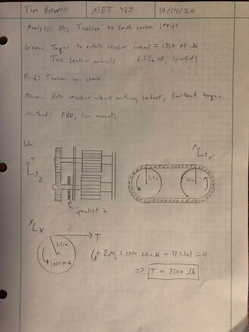
Analysis 6 was done to find the tension in the chain just to crush the carbon fiber (Not tension from maximum reduction system torque). Using the quantity of 1948 ft-lbs. found in the previous analysis, the moments about the origin of the sprocket where summed and T (Tension) was solved for, resulting in a tensile force of 7500 lbs.
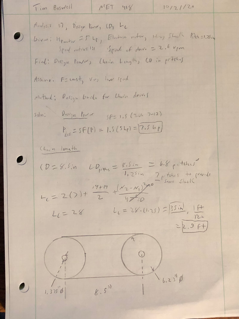
In Analysis 7, a few useful pieces of information were found. First off, the design power was found to have for future reference. When designing a chain or belt drive, this is often one of the first pieces of information found so that is what was done here. Then, the current center distance of the shafts that the sprockets will ride on was converted to length in pitches. Once this was found, the length of the chain in pitches could be easily found and converted back to length in inches/feet. The final result was 2.9 feet in total length. The resulting design parameter from this analysis means that a chain with a minimum of 3 feet in length must be purchased.
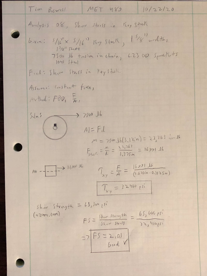
Analysis 8 was done to find the shear stress in the key stock that will be used. The keyway size for the sprocket and shaft comes out to be 5/16” by 5/16”, and the length of the key stock in contact with the sprocket is 1-5/8”. The moments around the origin of the sprocket were summed to find the torque that the sprocket would face to crush the carbon fiber, and then the force at the neutral axis of the keyway was found using F=M/d. Once the force was found, the average shear stress formula was used to find the shear stress (32,460 psi). The shear strength of 1045 steel is 65,300 psi, so there is a factor of safety of 2.01, meaning the size of the keyway should be sufficient for the application.
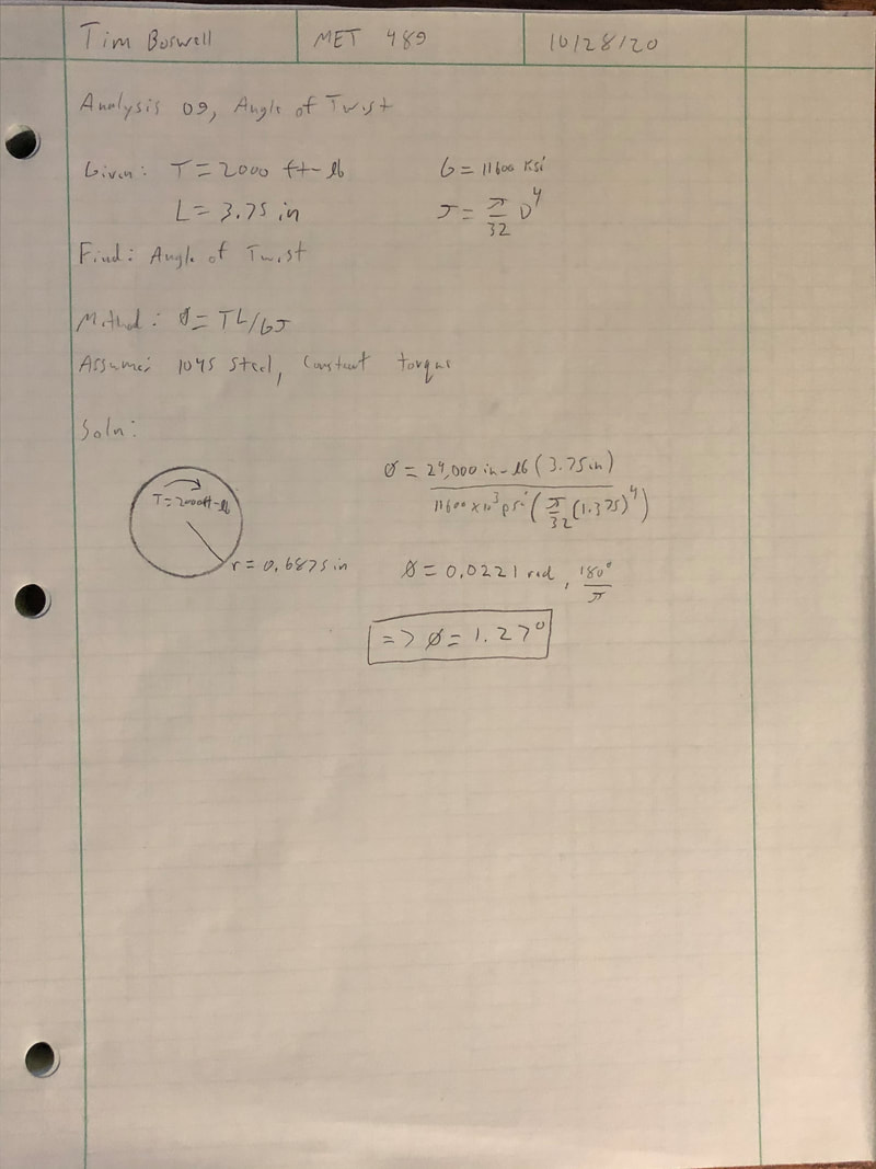
In Analysis 09, the angle of twist for the smaller diameter of the crusher shaft was found using the equation . It was found that the angle of twist in the shaft, when 2000 ft-lb. of torque is applied, is 1.27°. This is important to know because if the shaft is twisting excessively, the teeth on the actual crusher wheels could bind. There is also a lot of elastic potential energy in a shaft that is twisted excessively, which could be potentially dangerous.
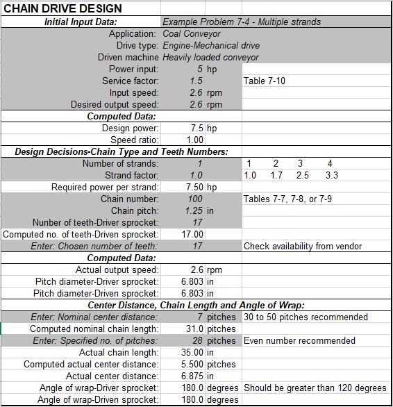
Analysis 10 is a chain drive design spreadsheet. This was done to lay out all of the specifications for what the chain drive will have. With the design that will be used, there should be plenty of angle of wrap for chain engagement with the sprockets. The actual length of the chain needed will be 35 in. or 28 pitches. Actual center distance comes out to 6.875 in.
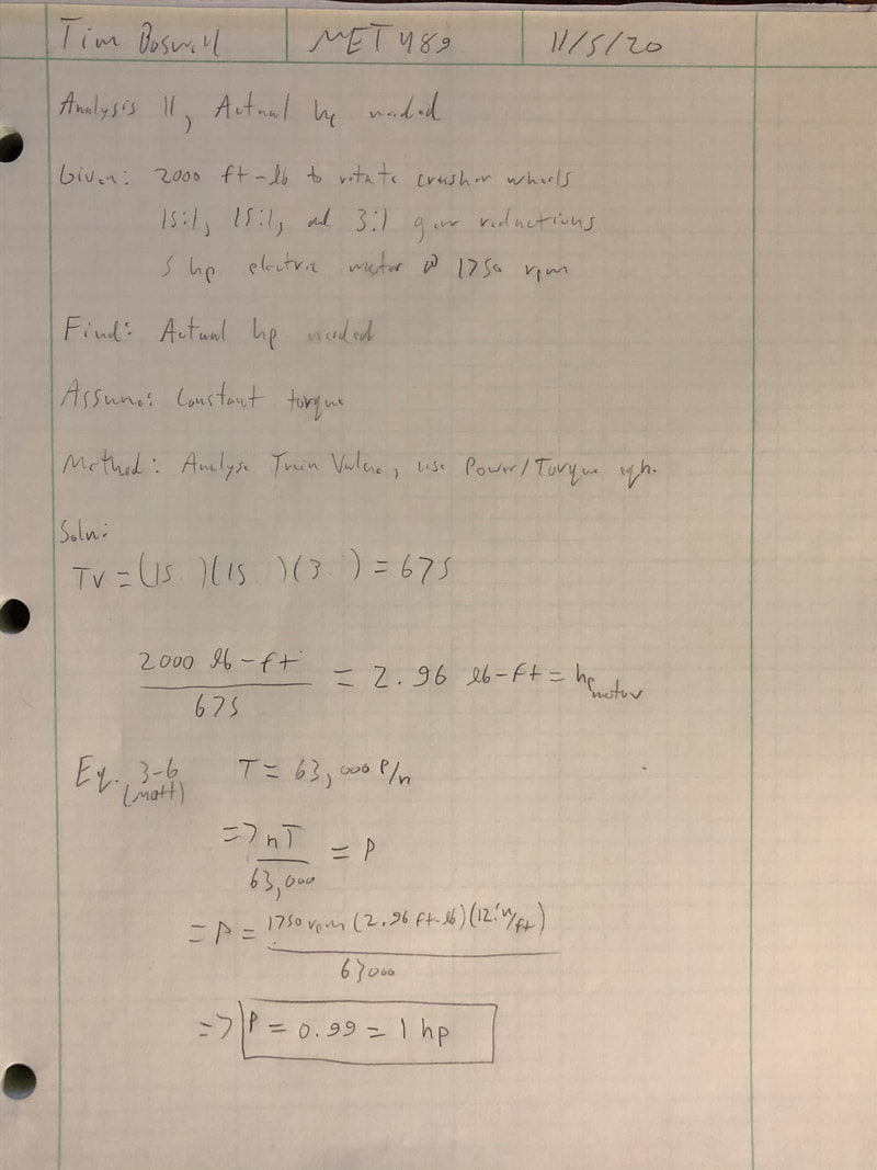
Analysis 11 was done to find the actual power need from the electric motor to produce the 2000 ft-lb. of torque needed to crush the carbon fiber. Using the equation T=63,000P/n, the equation was solved for P to give P=(nT)/63,000. The torque and rpm and were simply plugged in to give a resulting power of 1 hp.
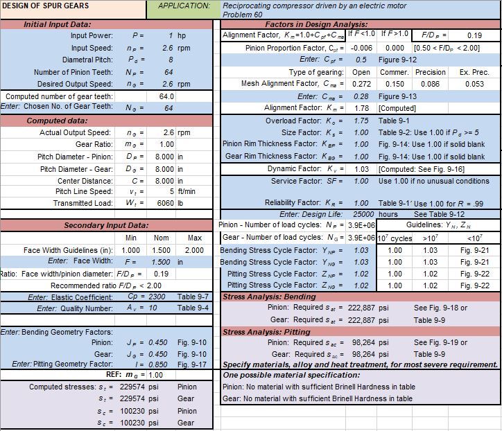
In Analysis 12 (Appendix A-12), the spur gear design spreadsheet was filled out to find the maximum bending stress and pitting stress in the spur gears. This very detailed spread sheet produces accurate stress values in the spear gears in order to specify a material to use. This spread sheet also incorporates safety factors into the calculation. The resulting bending stress in the gears is very high at about 220 ksi. This analysis shows that the current material for the existing spur gears could be problematic, and the material may need to be changed.
Analyses have been inserted below:
Analysis 1
Analysis 2
Analysis 3
Analysis 4
Analysis 5
Analysis 6
Analysis 7
Analysis 8
Analysis 9
Analysis 10
Analysis 11
Analysis 12